Introduction
Water Ticker is a simple water device to provide water usage information via a flow sensor or plurality of flow sensors also provide flexible and quick installation and re-installation.

Fig 1A : perspective of water ticker
|

Fig 1B : perspective of water ticker
|
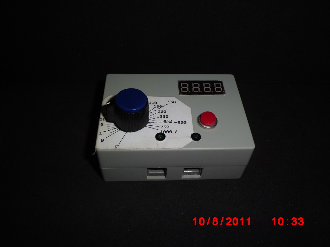
Fig 1C : perspective of water ticker
|

Fig 1D : perspective of water ticker
|
Hardware
Parts list as follow:
Parts list as follow:
|
Description
1. Enclosure box (90 x 65 x 35 mm ) 2. 9volt battery clip 3. LED light holder 4. Rocker switch (on/off switch) 5. LED 3mm (green) 6. Potentiometer (1K ohm) 7. Push button 8. RJ11 (female) 9. Turning Knot |
Qty
1 1 2 1 2 1 1 2 1 |
Unit Cost S$
2.50 1.00 0.40 1.00 0.30 2.00 1.50 1.00 0.90 |
Total Cost S$
2.50 1.00 0.80 1.00 0.60 2.00 1.50 2.00 0.90 |
Electronic
Parts list as follow:
Parts list as follow:
|
Description
1. 7- Segment LED ( 4-digit, cc , RED) 2. Audio buzzer 2kHz 3. Resistor 330 ohm 4. Resistor 1km 5. Resistor 10k ohm 6. Voltage regulator 7805 7. PIC 16F887 8 Trimmer 10k 9. Capacitor 0.1uF 10. Crystal Oscillator 20MHz 11. Transistor BC557 12. Electronic Board (through hole) 13. IC socket DIL (40 way) 14. IC socket SIL (10 Way) 15. battery clip 9 volt |
Qty
1 1 8 3 9 1 1 1 3 1 9 1 1 2 1 |
Unit Cost S$
3.00 0.80 0.10 0.10 0.20 0.50 4.00 0.44 0.30 0.80 0.30 1.00 0.40 1.00 1.00 |
Total Cost S$
3.00 0.80 0.90 0.30 1.80 0.50 4.00 0.44 0.30 0.80 2.70 1.00 0.40 2.00 1.00 |
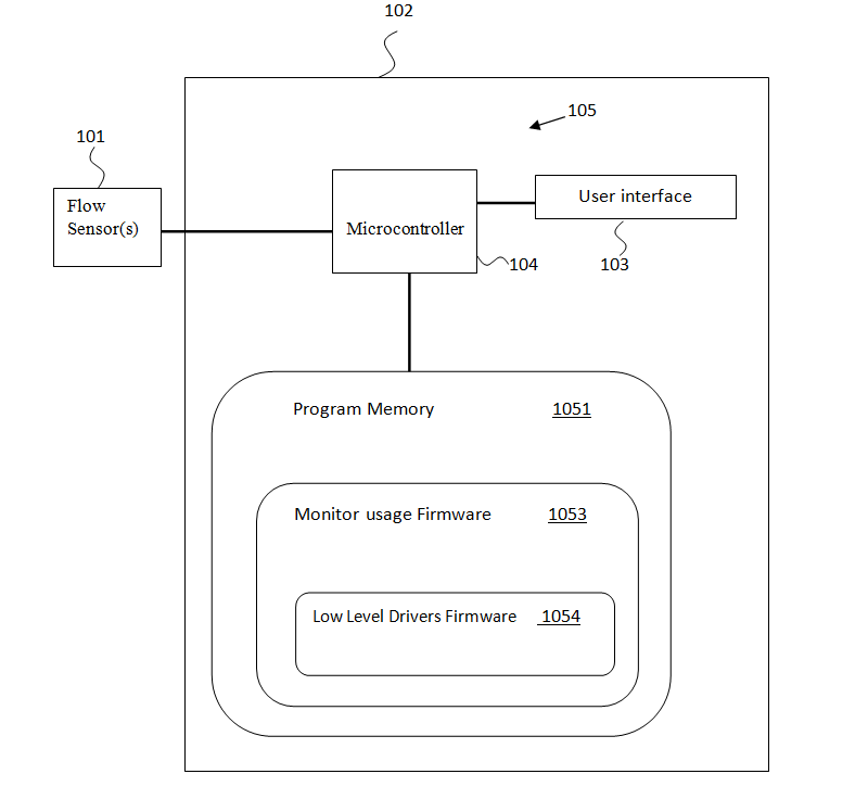
Fig 2A: An illustrates schematically a block diagram of an electronic monitor system for a water ticker
|
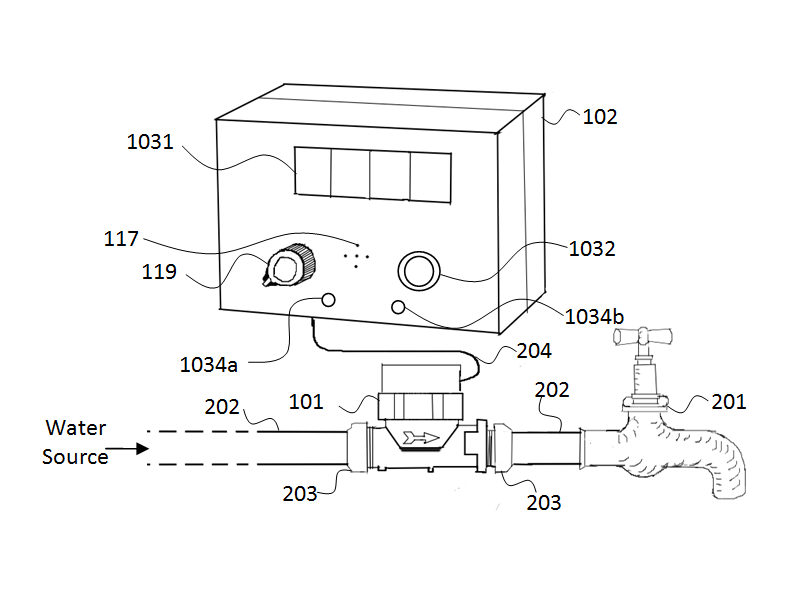
Fig 2B : A perspective of a water ticker use with a flow sensor and water tap.
|
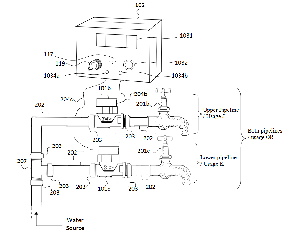
Fig 2C : A perspective of a water ticker use with two flow sensors and two water taps
|
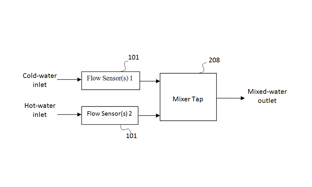
Fig 2D: Block diagram of two flow sensor apply to mixed tap.
|
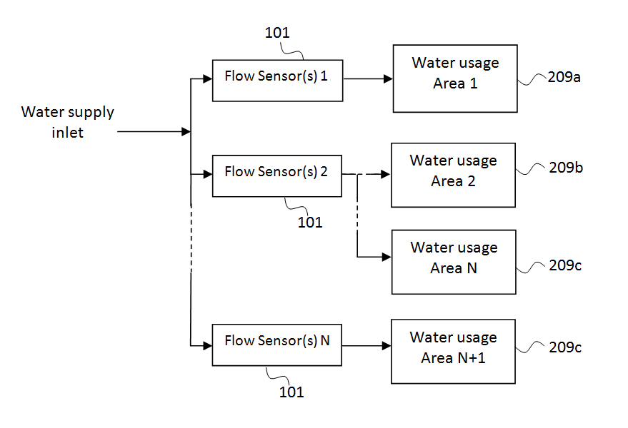
Diagram 2F: Block diagram of a flow sensor or flow sensors apply to water usage area or water usage areas
|
Explanation
Fig 2A. An illustrates schematically a block diagram of an electronic monitor system 105 for a water ticker 102. The electronic monitor system 105 consist of a micro-controller 104, user interface 103 and program memory 1051. The program memory 1051 consist of Monitor usage Firmware 1053 and low level drivers firmware 1054. The micro-controller 104 can be PIC microchip or ARM, Atmel AVR product alike. The user interface 103 consist of buttons, knob, buzzer, LCD display and LED light .
Fig 2B, A perspective of a water ticker use with a flow sensor and water tap. Briefly explanation of external part use, 7-segments 1031 to display amount of water usage in litre/gallon. Air hole 117 that all sound to pass through. Adjustable knob 119 allow user to set parameter. Push button 1032 for selecting. LEDs light 1034a and 1034b to indicate which pipeline are active. Demonstrate how can a flow sensor 101 install along a water pipeline 202 and connect the flow sensor 101 to the water ticker 102. To make simple for user to install the cable of flow sensor 101 is clamp with RJ11 connector and connect to water ticker 102.
Fig 2C, A perspective of a water ticker use with two flow water sensors and two water taps. The water ticker able to use with shower pipeline (dual pipeline) and able to compute water usage which illustrates in Fig 2D.
Fig 2D, Block diagram of a flow sensor of flow sensors apply to water usage area of water usage areas. The water ticker 102 able to use in an large area, example: canteen, food court, washing area and alike. The water ticker 102 can also act safety device to check any leakage along the pipeline.
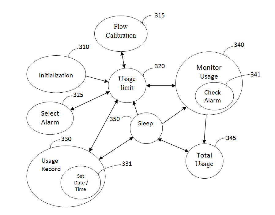
Fig 2G :State Diagram of electronic monitor system
Fig 2G, State diagram of electronic monitor system. First boot up stage is initialization stage 310, system will boot-up and update various parameter that previously set . After initialization 310 stage proceed to usage limit stage 320 is to set water usage limit, lowest water limit able to set is 0.1 litre which is equal to 100 millitres and highest limit able to set to 1000 litres.
Assuming everything is been setup as in Fig 2B, user need to calibrate the flow sensor 101. Turn the knob 119 to anti-clockwise till display 1031 show "FFFF" and push 1032 to enter calibration mode. Turn the knob 119 to "FF1F" to calibrate flow sensor 1 and "FF2F" to calibrate flow sensor 2 and push the confirm button. The electronic monitor system 105 suitable for pulse signal, refer to manufacture manual of flow sensor. Example: Number of pulse per litre = 100 pulses, then set the number of pulse to 100.
After selecting the pulse, push the confirm button 1032 to confirm. To go back to usage limit stage 320 turn the knob 119 to anti-clockwise till display "----".
In usage limit stage 320, user require need to turn the knob 119 and select the water usage limit, after select push the button 1032 to confirm. As mention early on, the range of water usage limit from 0.1 litre to 1000 litires. In monitor usage stage 340 is to monitoring water usage will explain later on. Select alarm stage 325, turn the knob 119 to "----" push the button 1032 to set the alarm for which tap. There are 4 choices, single tap alert mode either one, both taps alert mode and no alarm alert mode, this base on theory of 'OR' gate function. The LED light 1034a and 1034b will indicate that alarm is on/off.
After setting the alarm, user can set the water usage limit in usage limit stage 320. Press the button 1032 to confirm. The system 105 will proceed to monitor usage stage 340. In this stage 340 will monitoring amount of water usage and in check alarm stage 341 is to check whether the amount of water usage is exceeding the user usage limit that was set in usage limit stage 320.
Next stage is the monitor usage stage 340, there is no detection water flowing after some time, then proceed to total usage stage 345. Total usage stage 345, will sum up total amount of water usage within the day, this feature allow user to aware about their water usage within the day. After display the total amount of water usage, the next stage will proceed to sleep stage 350. In sleep stage 350, power consumption for the electronic monitor system 105 is at low level.
In sleep stage 350, there two ways to wake up the electronic monitor system 105. First way, is the system 105 detect water flow, this action which cause by user turn on the water tap 201. Another way is through user interface, user can turn the knob 119 to select different water usage limit. Do take note, during selection of water usage limit if user using water tap it will also recording water usage embedded. User may wish to check the water usage limit, just press the button 1032 to awake the system 105 and the system 105 will display 1031 the total amount of water usage. After a day or 24 hours, the system 105 will record the total amount of water usage in memory in usage record stage 330.
In set date/time sub stage 331, assuming the system 105 is at usage limit stage 320. Turn the knob 119 till display 1032 show "FFFF" and press button 1032. After that turn the knob 119 clockwise direction, the most right significant digit will show "D-xx" on display 1032 mean set date function. Select the date range 1 to 31.
Next is to set time, assuming the system 105 is at usage limit stage 320. Turn the knob 119 till display 1032 show "FFFF" and press button 1032. After that turn the knob 119 clockwise direction, the most right significant digit will show "H-xx" on the display 1032
mean set time function for hour. Select the date range 1 to 24. After hour is set,will follow by set minute and the display 1032 will appear "M-xx".
Scenario One: user want to fill a bucket but do not have ideal how much amount water he/she needed, after he/she first try with the water ticker he/she realise 3/4 full is about 7 litres. So next time he/she set the usage limit to 7 litres and let it fill up, whenever the amount of water flow over 7 litres the electronic monitor system 105 will alert user.
